

THOR Racing
-
Posts
687 -
Joined
Content Type
Profiles
Forums
Store
Blogs
Events
Downloads
Supra Articles
Gallery
Everything posted by THOR Racing
-
No not strictly true. Just changing the fuel will be O.K. but the amount of retardation in the ignition timing system added in, due to the low RON normal uneaded, will take a finite time to be removed back to a figure most suitable to the Super Unleaded. The car will sample the Knock detectors and after a while will advance the ignition a little. If the engine detects no knock then it advances some more, and so on and so on. This obviously takes some time. Now the alternative is to remove power to the ECU for a short while. The ECU forgets the retarded ignition setting and must restart from the default programmed in from Toyota. This for the Jap cars assumes 100RON I guess. So this time it' likely that the car feels more responsive as you've suddenly removed all retardation and possiby advanced the ignition system beyond what even Super Unleaded can cope with. So again the knock detector detects knock and retards the ignition again. But this time only a tiny amount,well less than for normal unleaded. So people remove the EFI fuse as it gets you a quick fix to the problem of the ECU relearning. It also feels better as the ignition advance changes a lot compared to the setting just before the fuse was pulled, probably hightened by the fact the ignition is too advanced anyway (just a guess that one). So if it's raining and you change to SUL, have a long cruise ahead of you then in about 50->100 miles it will have adaped anyway and you don't get wet. But if it's fine and you want instant "whamo!" then remove the fuse for a bit. Regards Pete
-
Correct. It'll be just like normal fuel cut but at 18psi. (But remember you can always remove it as well if you're in any doubt) I'd recommend NGK 6097 (BKR7E) As for the other things do you have the following.... Super Unleaded Fuel? (If not why not!) Racelogic Traction Control? (Could be harsh traction setting and wheel spin) Also consider that fuel cut only cuts in after a prolonged period of exposure to high boost. I think it's something like 2s. i.e. you have to be at or above the fuel cut threshold for longer than 2s before the ECU kicks in. It may be that due to and uncontrolled boost system it's peaking above 1.1 for a short time, poor fuel or just plain bad luck is causing problems, the boost gauge is damped so maybe wouldn't see this slight peak rise in boost above 1.1. Just ideas..... Regards Pete Regards Pete
-
No, you misunderstand The difficulty is finding enough information about the sensors heater characteristics and drive current and voltages for the Nurnst pump Cells inside. Great if you have a Motec as they've done the research and have electronics which work with multiple WBO2 sensors. Not so good when you are trying to make one yourself from stratch. That's all I meant. I have a datasheet from Bosch and it's a little difficult to follow. assumes you know how to interface to them in the first place. And the DIY EFI WBO2 project won't work with it. Or rather I'm too scared to try and waste £60 a pop. I'd rather learn how they are meant to be driven first. It may be possible to modify the DIY EFI version but again it assumes you fully understand the WBO2 technology. I'm sure is not rocket science, but somethings always hard until you learn about it. Then a big fat "Doh!" reverbs around the room!!!! Pete
-
compared to the Bosch ones at £60! USD to Pounds normally works out to be the same when you've paid the duty. This is assuming it was a commercial venture and you have to pay all duties. I'm sure the individual could source one for the dollar equivalent if sent on it's own in a plain jiffy bag. Pete
-
I would say for a completely standard Supra that normal unleaded is fine. I won't say you'll be getting the best performance out of it but it won't damage it in my opinion. BUT... isn't that why you brought a Supra I found it a false economy when my Supra was standard. With Super it went further than on normal UL so the extra cost of the Supra was easily justfiable. But if you cannot get Super then normal is fine on a standard Supra as it has enough learning ability to retard the igntion to reduce any knock associated with the poor fuel. Regards Pete
-
Yes. And I made the DIY EFI version of the WBO2. But the NTK sensor is mega expensive. Bosch do a wideband sensor that is 1/2 the price but finding out how to properly use it is proving difficult. It's definitely on the cards. Pete
-
Yeah right !!! So do you have any diagnostic trouble codes stored? i.e. is the engine check light on or does the OD light flash or something? I would have thought that Toyota would follow the same method of DTC retrieval as for all other Toyotas. Do you have the MkIII engine manual that descries the DTC procedure? Pete
-
I've got Eibach Springs (about 25mm lowered I guess) KYB AGX Adjustable shocks (4 settings, adjusted via top mounted rotary dial) KYB Picture1 KYB Picture2 KYB Picture3 KYB Picture4 Regards Pete
-
Just a quick note to say I've updated the installation details on my site. It now includes details for the non-VVTi and VVTi Supras, plus MR2 and Celica. MkIII Supra coming soon and many other cars when I have time. TRL VFCC Thanks Pete
-
Cheers guys. Supra_Al, drop me an email on [email protected] if you're interested in the Fog conversion (Fcon) kit. OR... just follow the wiring diagram freely available on my site. TRL Fcon All I provide is the fully wired up relays. You have to wire them in of course. Saves you working out how the relay bit works I guess. Regards Pete
-
Umm? The wideband sensors have a more linear output characteristic than the narrowband. But they pretty much give the same outputs. This sounds more like the signal conditioning circuitry is amplifying one WBO2 sensor to be in the range 1.8->2.8 and the other 0->5V I don't think it neccessarily holds that if you have 200 points for the 1.8->2.8 you can interpolate this and get 1000 points for the 0->5V one. It's all down to what is measuring the voltage. Most of these devices will use some form of analogue to digital converter and it's this arrangement that determines the resolution accuracy of the WBO2. So for an 8bit ADC you get 256 points. But it might be that they arranged it so that not all the available range is used by the ADC and therefore the WBO2 output only covers 200 points and not the full 256. Given that you use the same 8 bit ADC with the other sensor 0->5V and adjust the input of the ADC you'll still get 256 points. Only when you go for a larger bit width ADC will this increase. e.g. 10bit ad you get 1024 points. So all in all you need to ask "What is the min and max AFR range?" (e.g. 0.7Lambda to free air) "What resoution does the device have" (0.05Lambda steps) Forget about exact voltages, they are meaningless without the relationship to the AFR. Regards Pete
-
May we ask why? What symptoms do you have that makes you think it the gearbox itself is the problem? Regards Pete
-
Just remember that even though one odometer is VFD (Vacuum Flourescent Display) and the other a mechanical rotary barrell that they are BOTH driven by the same electrical signals from the speed sensor. The mechanical unit just uses a stepper motor inside to translate to rotary motion. So the same principles apply to the Jap spec pre-facelifts and the facelifts when converting KPH -> MPH. Regards Pete
-
I use 10W30 Valvoline Synpower Fully Synthetic oil. http://www.valvoline.com/pages/products/product_detail.asp?Product=19 Had no end of oil burn with 0W40 Mobil 1 and as soon as I went to Vavoline I get about 1lt used every 5-6K miles. i.e. way before I change the oil anyway normally (3-4K) It's also a hell of a lot cheaper than Mobil1 I got a job lot from TorqueIC but I think Leon does it as well now, but in big drums. Regards Pete
-
Andrew, This sounds like the recirulation valve. (The stock BOV) Shiny thing that looks like a top hat. I wouldn't think it makes any difference which way up it is, gravity may play a small part in it though as a vacuum on the small hose causes the diaphram inside to move and the valve open. Might make it slightly harder to move if upside down, but I don't think anything significant. Regards Pete
-
Nick, No this just means your fog lamp switch is cr*p! A good switch should make a clean contact and have minimal electrical interference. The problem is the switch is carrying the load. Better to have the switch turn on a relay and have that take the majority of the current flow. Pete
-
Funnily enough I have "exactly" the same problem. But as I've had a dash fuse blown for a while now I guessed it was that. (been too lazy to replace it..doh!) I know I have a dash fuse blown as I was mucking about with my fog lamps and behind dash wiring when it blew. The odometer and clock both distinguish when I put the lights on and I get no lighting behind the speedo dials etc. The radio interference bit is very odd I agree. So I think the power return (or ground!) is being found via a strange route hence the interference. I need to take a look in the next couple of days and replace the fuse but I'm hoping it's just that. Regards Pete
-
Welcome to the list.... HKS FCD. Scales the MAP pressure signal and clamps below fuel cut threshold. Allows you to boost your turbos above the Toyota ECU settings. I will not comment on it being good or bad as I sell an alternative and this would be unfair/biased. The valve that sits between the turbos and recirculates the pressurised air back to the air intake during throttle off. To prevent build up of back pressure on the turbo blades. This sounds like a replacement Toyota spec one. That's fine as many at this age don't work anyway. You'd be suprsied how many people drive around with non-working recirculation valves (luckily they fail safe) Electroinic Valve controller (not quite sure on exact name) BUT it's an electronic boost controller. Allows you to control the amount of boost your turbos generate and hence how much power the car generates. Sounds like the Sequential BOV (as suggested already) Works in the same way as the recirculation valve but dumps it's air to atmosphere and not back to the air intake. A bit of an overkill but doesn't hurt, plus they sound great. I have one and removed my stock recirculation valve. The VPC (Vein Pressure Converter) simulates the MAF (Mass Air Flow) meter which you used to have in the air intake, causing a small restriction in the intake air flow. This now means that the BOV to atmosphere is O.K. There is an argument that dumping pressurised air to atmos' will give faulty air/fuel calculations when a MAF is fitted. I'm assuming the VPC takes care of this. Don't know on this. CAMs are not my thing. Anyway, Nathan (representing TDI) will be along at somepoint to put you straight. Regards Pete
-
1: If the big red triangle and engine warning light appear along with a large jolt then it's likely to be fuel cut. 2: If it's a progressive slowing down, stuttering then it's likely to be plugs. Fit NEW and go one grade colder. 3:If it just won't go past 112mph then you have the top speed limiter still and need to remove it. Email me on [email protected] for 1 and 3 resolutions. 2: can be sourced from JPS Motorsport, Torque IC, TDi or yourself directly from a motor fator. You need NGK 6097 (BKR7E) for example. Regards Pete
-
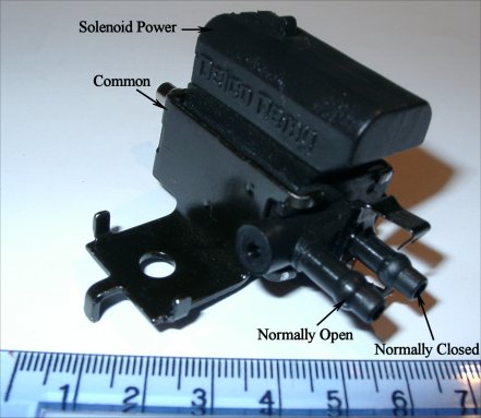
Just an update. I've found with the help of a Darren a Lotus solenoid valve. Still switched and powered in the conventional way like the Apexi valves are (pulse width modulated @12Hz (or something like that)) Here's a picture of it. I'm going to try it as a replacement valve for my Apexi boost controller to see if it performs as well. I've also found replacement Apexi valves as well. Actually sold by Autronic but are expensive at £65+VAT Regards Pete
-
If it's hoses and 2nd turbo then I always check the tiny little hose connecting the VSV to the exhaust bypass actutor. It's about a 4m pipe, so tiny but can leave you without any 2nd turbo spoolup. Look at the exhaust, follow it back to the engine, you see the O2 sensor. further up is a mechanical valve and actuator arm. Follow this arm to the actuator and check the pipe from it to the VSV, which itself is located close to the front of the engine with the boost control VSV. Regards Pete
-
just poped along.... The signal is a sine wave from the speed sensors generated from passing a magnet past a sensor. The magnet induces current into the sensor and this is turned into a voltage. The signal will be low amplitude at low speeds ( Problem with most electronics expecting a square wave input is that the ABS or wheel speed sensors generate an AC sinusiod waveform which they don't like and chances are it'll only start to roughly work when going quite fast (if at all) I made a signal conditioning circuit to adapt to Rob's ABS sensors for his VVTi in order to do the speedo conversion. The same thing would be needed here. The signal needs to be decoupled and biased around 2V. Now the AC waveform will move about 2V, and 2V is the triggering point for most digital circuits. Add a Schmitt triggered gate in between and you have yourself a 0->5V pulse generator from the wheel speed sensors. I guess you'll now ask ...... can I make one and how much? PM me on this. Regards Pete
-
Can someone help me with this compressor map?
THOR Racing replied to Adam W's topic in mkiv Technical
Check out Auto Math Review and pretty much the same review at Amazon. Another Review Pete -
oh and "whoever you spell it" was meant to be a joke!
-
Rob, the AFM is the black box situated in series with the air filter. It's a device that measures air flow (Hence air flow meter) and like anything that makes a measurement it will always affect the thing you are measuring. (to some degree) I cannot remember whos principle that was (someone famous in the science world) Was it Heisenburg or whoever you spell it? Any way because it's situated actually within the air flow it will cause a slight restriction to air flow. So when you start upping the mods and expect more air to flow into the engine then the AFM can be a retsriction (much like the CATs on the exhaust) How much of a restriction and how much is just tuning crap I don't know. Never tried it. What the Vein Pressure converter does is replae the functionality of the AFM with a box and a MAP sensor. In Physics the gas laws relate mass of air, temperatures and a whole lot of other stuff together and an AFM measures the air flow and outputs data in one format. The VPC tries to replace this by using a MAP sensor on the throttle body to simulate the measurement made by the AFM (that used to be in the air inlet side, but you've removed to get rid of the restriction). Oh and calm down Mark Regards Pete
