

THOR Racing
-
Posts
687 -
Joined
Content Type
Profiles
Forums
Store
Blogs
Events
Downloads
Supra Articles
Gallery
Everything posted by THOR Racing
-
Too true! Forgot that little bit.....Doh. Anyway this assumes we all KNOW how they designed their electronics inside. I was always planning to see how they isolated the injectors incase of power failure of the RLTC. I would hope that even if the box burnt up that the injectors would always default to the original ECU control. (i.e. imagine a bank of relays inside which when energised switch in the RLTC but when power is lost (or RLTC is OFF maybe) they relays always fail safe and allow the stock ECU to take over. Regards Pete
-
Could it be that as the calibration didn't go well to begin with that it has the WRONG reference wheels set up? i.e. the ABS wires are just coloured and RL don't indicate which wire is for which ABS sensor as this is normally derived from the calibration proceedure. If you've been mixing up DAT files, could it be the RLTC is now confused as to which wheels are driven and which are reference? Just a thought. Can you confirm this part of the cal' went O.K. ? Regards Pete
-
I think because it was so simple no one mentioned it. IT's just a case of filing away some of the mounting plate to make the bulb fit. I don't think it's hard. Just buy a bulb and offer it up. Try checking the following is set in your browser. (Assuming it's IE) Tools:Internet Options:Temporary Internet Files: Settings Check for newer pages,..... ensure the (AUTOMATICALLY) radio button is ticked. Regards Pete
-
Did you transfer the wheel reference data from the original Dat file to the new updated file? You need to run the standard file and get the wheel calibration done, upload the dat file and then transfer the reference data over to the new dat file and then download the new one. Well that's what I thought you had to do. Anyway Jon's RLTC doesn't want to communicate so I hope it's this RPM wire. Just to clarify.... the device itself wasn't faulty it was the cable which was intermittenly connecting to the header pins on the circuit board. So the Design is fine, just the manufacture was faulty. Regards Pete
-
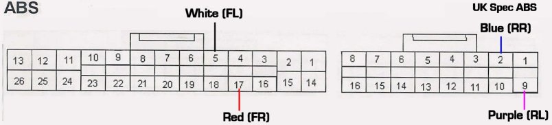
OR the non-VVTi ABS unit for the UK Spec Supra...
-
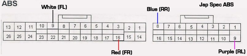
NOT to be confused with the non-VVTi ABS unit for the Jap Spec Supra...
-
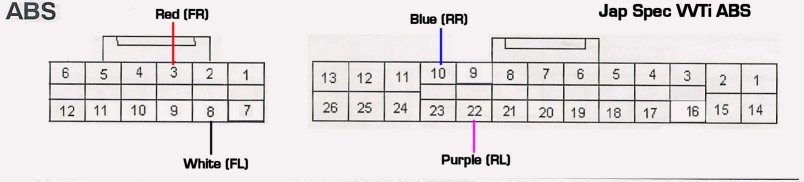
Jon asked me to fit the four ABS signal wires to the ABS unit as the ABS unit in his VVTi did not match any datasheet with the RLTC. My findings were as follows. (Measured with an oscilloscope, car jacked up and spinning the wheels by hand) Regards Pete
-
I'm assuming you're referring to the Greddy BCC device? This device is not adjustable in that sense. It will illiminate the fuel cut that happens at 15psi and that's it. Any adjustment is for different cars. If you were refering to the TRL VFCC then you can adjust to a MAX of 19psi (which is a limitation of the stock MAP sensor and not the VFCC) OR set it to any value from 15psi to 19psi. It's in about 0.5psi steps. Regards Pete
-
Si, Hello and welcome. Try using the search facility at the top right of the screen. You have mail (PM) on the subject from me. Regards Pete
-
Simplest thing to do is WAIT! Wait until you've fitted the exhaust and IF you hit fuel cut 1: You'll know you're at or above 15psi boost 2: You can fit a fuel cut defencer to remove this If after looking at your boost guage you decide that say 16psi (*) isn't enough then fit an electronic boost controller. NOTE: (*) that was a guess, sometimes the exhaust de-cat gives you 18psi other times it doesn't. Suck it and see as they say. If it's too low you'll need a boost controller (Either manual bleeder valve or electronic) This is the simplest and foolproof method. Saves wasting money unnecessarily all in one go. Guaranteed you'll want it all by the time you get used to the extra power that the de-cat gives you. No one can tell you 100% what will happen. De-catting is a little variable from car to car. Regards Pete
-
Actually it can be adjusted by anyone (the user). It's set by default to be 18/19psi but if you don't like living that dangerously then you could set it to say 15.5, 16, 17 psi etc etc See graph on the site. 19psi is about the max as the MAP sensor maxes out at around 4.95V which is around 19psi. You could fit a 3bar MAP sensor and scale the output for the ECU but use the extended range output with the VFCC to give you 22psi overboost protection (or again whatever you like). I've often thought about making something like this. i.e. replacement MAP sensors that allow greater range of VFCC control. Thinking about it I'm sure I could use the existing MAP sensors used on the multitude of boost controllers out there.......just thinking out aloud. So even the high boost guys would have fuel cut protection. Regards Pete
-
Just to wet your appetite. Take a look at TRL's new product range. Finally I've got around to deciding how it will look and feel. So gone is the gameboy look and in with the multi-platform (Palm, Laptop,Desktop, Pocket PC all IrDA or Bluetooth connectivity) Hopefully I'm teaming up with another Automotive company to be able to finance this project. But just so you know what's to come late this summer I hope. Really pushing for demos at present. TRL DCX-infinity range of Digital Controllers I know it's not strictly technical but you guys are the ones who are hopefully going to use it. It's work in progress so no comments on functionality or operation. It's just a taster of things to come. Regards Pete
-
These were the part numbers I used to get mine. (But a 1995 MkIV) http://homepage.ntlworld.com/peter.betts/supra/TechTips/rubbers1.jpg from page http://homepage.ntlworld.com/peter.betts/supra/TechTips/rubbers.htm Regards Pete
-
Yes 100%. (assuming speed delimiting at the engine ECU is all you want to do) The Speed signal wire at the "engine ECU" is the Pink with Silver Band more specifically located E10(2) NOT E9(2) as they suggest. The speed signal coming from the speed sensor (attached to the gearbox) is the red and blue wire, this goes into the odometer and becomes the pink and silver banded wire. It is the pink wire that is distributed throughout the entire car. You never see the red and blue wire carrying speed again! If you've modified any red and blue wire you've modified the wrong signal. God knows what it's done. Complain but don't give the correct information. Why do their job for them. I spent a lot of time (and many others on this list) gathering such info so if they cannot be bothered to research it themselves or understand even the FREE stuff I've posted then they are not worth helping. It couldn't be clearer on my site I don't think and still they copied it wrong. Not sure why your cars smoking. Regards Pete
-
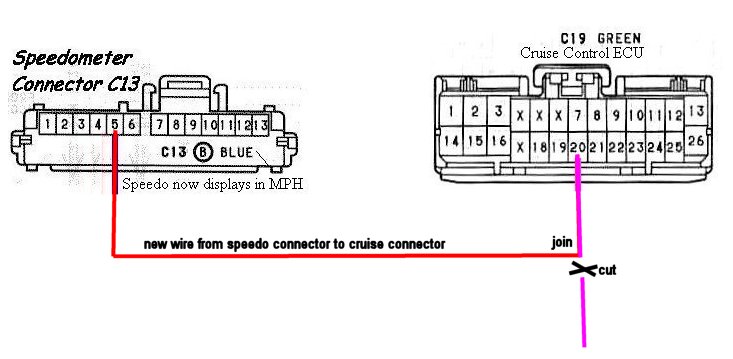
I'm sorry but the instructions are TOTAL BO**OCKS! I have never heard such CRAP! in all my life, talk about confusing!. Where's the pinout drawing of the ECU and a nice little diagram? PLUS!!!!!! and I'm PISSED OFF HERE! It's my flipping connector drawing at the top! (Which incidentally has no relation to fitting a top speed delimiter! I wouldn't mind if they'd scanned it in from the Toyota Manual and then added their own wires but that's my text saying SPEEDOMETER CONNECTOR C13 and MY COLOURS! They were never meant to relate to ACTUAL wires on the LOOM! They've cut and paste my JPG image and added their own text. Which is confusing to say the least. And I know how to do it! I've said BEFORE! Use my CIRCUIT diagram!!!!! http://www.trlperformance.com/dsc.html For specifics see below..... ALL you need to do is know which wire from THEIR BOX is 12V, 0V, Speed Input and Speed delimited Output. 12V and 0V are easy! . Speed signal is EASY! IT's the PINK!!!!! wire in the top right hand corner (has a silver band) Insert the box in SERIES with this wire! Using the diagram at MKIV.COM You'll see E10(31) = 12V E9(69) = 0V E10(2) = Speed Sensor input (i.e the one you need!) Who are these shower! I've a good mind to give them a piece of my mind! PROMISE you'll never cross their palms with silver again. Regards Pete
-
normally the flux is impregnated into the solder core. Well nowadays anyway. So, so long as you don't spend a lifetime heating the same bit of solder and burn all the flux away before you're made a good joint you'll be fine without seperate flux. IMO But we digress..... Regards Pete
-
4 wires is fine for an auto and manual. Just need to find out what they mean. I guess, red = 12V black = 0V grey/yellow = input/output or vice versa. (Best to make sure with manufacturer.) What more do you need to know? Just fit it to the ecu. Regards Pete
-
Could it just be heat soak or ambient air temps? It could just be the air temps under the bonnet or the incomming ambient air was a little warmer (as yes we've had a couple of warmer days now). Obviously warmer air means less dense air charge and hence less bang! Especially at higher RPMs as the turbos heat up the charge and make the intercooler work really hard. Try it on a cold morning... does it do the same? Plugs could be a factor which is being accenuated by the leaner mixture, higher ambient air temps. Do you have a replacement air filter? Could be heat soak over such a long journey and again IC cannot cope. I'd recommend getting your car dynoed on a nice warm sunny day. Then you know if all is well, then that it'll be fine all year. Never trust a dyno done in winter to last all year! Regards Pete
-
so sorta-like this...... Pete
-
Yes. Although I thought it was Pink (Maybe my camera colour isn't quite right) and to locate the correct wire to use from your converter. 1/ First find the converter (probably behind the speedo head) 2/ locate the wire from your box going to your speedo that feeds to the same point as the white wire on the DSC diagram does 3/ use this wire to connect to the connector side of the Cruise plug, leaving the loom side disconnected. Looking at the DSC wring diagrams you'll see the correct PIN to locate the wire to on the CRUISE plug. It should be a Pink with silver band wire. But whatever the colour it's the pin location that is the key. Regards Pete
-
Sort of like this, only without a relay Pete
-
Everyone else has pretty much said it all. If you have a speedo dial face that reads 0->110MPH then the face has been changed from the original 0->180KPH Jap unit to a cheapo MPH one. If the speedo dial face reads 0->180 with a MPH sticker over the Km/h legend then this is the BEST situation and most common. The fact the odometer displays MILES and clocks up in miles could indicate.... 1/ Jap odometer replaced with UK spec Odometer. In which case the miles displayed could be anything. No idea how you confirm that. 2/ speedo converter fitted which is ONLY converting the Jap odometer. In which case the number displayed is a combination of the Km and new Miles traveled Ideally you need to get a 0->180 speedo dial.... 3/ if it's a KPH one then you fit a speedo converter and cover the Km/h legend with a MPH one. 4/ if it's a MPH UK spec one then great, you don't need to do anything to the signal for the speedometer. BUT if it's 4/ then you will need to buy a converter (or work out what's fitted) to convert the odometer, unless the odometer is a UK spec one (in which case you need do nothing) It all sounds very complicated but it's simple really, but the key is finding out EXACTLY what you have got fitted NOW! That's down to you. Then we can help and provide more exact details. For speedo converter and combined top speed delimiter try TRL DSC+SLD There is also more details on my personal site on speedo conversion which I suggest you read. Pete's Speedo Stuff Click on "Speedometer Conversion" section Regards Pete
-
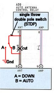
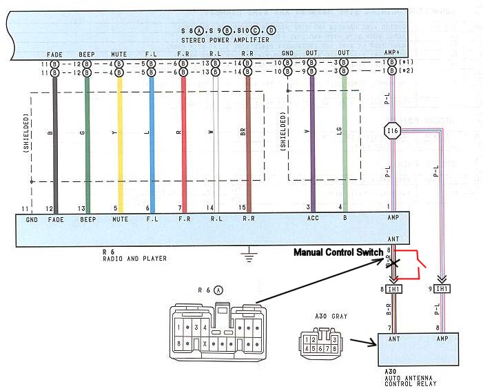
and the WITH AMP picture....
-
Try doing this..... Placing a switch in the power feed to the auto-antenna as shown on the attached drawings. Radio WITHOUT the power AMP. "antenna_control.jpg" (Attached to this posting) Radio WITH the power AMP. "antenna_control1.jpg" (Attached to next posting) No idea if it works, just thought it up. Regards Pete

-
There are a set of pictures to download inside a self extracting ZIP file on the site to help. One picture is of the cruise control location and connector DSC Page with Download Pictures Have fun. Pete


