

Barnstormer
-
Posts
76 -
Joined
Content Type
Profiles
Forums
Store
Blogs
Events
Downloads
Supra Articles
Gallery
Everything posted by Barnstormer
-
thanks for the info. Called the local Toyota parts guy who is normally useless and found that he'd been replaced by a new man who has a Supra! Anyway, he reckons he can get me a complete new assembly for £15 +vat by Sat. hopefully the fitting won't be too difficult. ATB
-
and another pic...
.jpg.de6a9017f587704571e78831687d0fad.jpg)
-
Just had someone bash my left bumper in Tesco's the other day and now need a new lens and gasket. Its on the LH bumper on my facelifted 97 j-spec. see below if anyone can help with some q's I'd appreciate it. 1. What is the part no. for the lens and gasket? 2. Is it the same as for a UK spec? My local Toyota dealer isn't too good with j-spec stuff... 3. How do you get the lens off? Is it pull off or is there some bolts on the inside of the wing? The bulb assembly is still intact and works OK.
.jpg.40bad7b824c0c7655b1947261e02b7ff.jpg)
-
if your talking about this page.. here then its about fitting a Supra SMIC to a Saturn! DSM cars are Diamon Star Motors (Saturn, Eclipse, Talon etc). Think its quite inventive installing a SMIC into the wheel well of one of these cars. Apparently a popular mod. However, i have no idea what the quality of the kit from this place is like - just found it while surfin. ATB
-
While surfin found this site... here Some parts for Supras as well. They do turbo kits, heads, fuelling etc. ATB
-
Just found this site - not sure if its been posted before... http://www.mohdparts.com/ some good stuff on e-mamange too... http://www.mohdparts.com/emanage/index.html Check out the FAQ's and manuals at the bottom. ATB
-
Accidentally met Hooper at the local Shell garage while filling up with Optimax. Car looks great especially the Lexus rims and the interior has been sprayed up as well. Needs a TRD spolier I reckon............. ATB
-
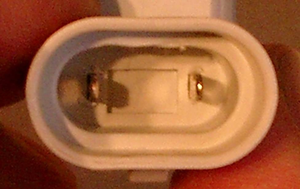
Here is the original j-spec bulb from the dipped unit. As you can see it only has a single ridge to fit the single groove plug connector. In the end only took 5 mins to do both plugs and was v easy.
.jpg.39f91bca0f7322b4f2dfe46484925a88.jpg)
-
I had some probs fitting the Phillips bulbs to my car. I bought 'em from Envy - Phillips bulbs HB3 I have a 1997 Facelifted j-spec mkIV TT auto and the HB3 bulbs fit perfectly into the main beam plugs without any modification. However, the dip beam do require the two ridges in the bulb to be machined out as they do not fit the electrical plug connector which has only a single slot. Here is the modded hb3 bulb I didE As you can see I used a dremmel with a milling bit to machine out the two ridges.
-
How much BHP do I get from water injection?
Barnstormer replied to wesmi01's topic in mkiv Technical
The Harrier can hover without WI but only when the ambient temp is low and the aircraft is light ie low fuel and no weapons. The main problem for a jet engine is density altitude - if the ambient temp is high and/or the air pressure low the thrust of the engine decreases. WI simply increases the density of the airflow so increasing the thrust. Most jet engines run at more than 100% thrust. Indeed the plane I fly today is rated at 108%! When an a/c engine is first tested and certified it normally has rated thrust ie 100% but often over time the engine manufacturers increase the design efficiency, thrust etc to give a but more oomph! Also a/c manufacturers increase the basic weight of an aircraft by adding bits and so the engines need to be uprated. If anybody is REALLY interested to know I can explain more but it won't help you get any more BHP from a Supe. ATB -
How much BHP do I get from water injection?
Barnstormer replied to wesmi01's topic in mkiv Technical
A lot of older aircraft did have water or water/methanol injection on turbo jet engines. Basically it did two things.. 1) Lower the exhaust gas temps (EGT) a little and most importantly 2) increased the mass flow through the engine resulting in higher thrust. Jet engine thrust is proportinal to the mass of air ejected out the back. As water increases the density of the airflow the result is more thrust. Normally only used on take off to get airbourne when very heavy or on a short runway. The Trident was an example of such a beast and in the cockpit were 3 green lights - one for each engine. When required to use the water/methanol injection on takeoff the co-pilots job was to watch the lights. If any one of them failed to illuminate it mean't you were not going to get airbourne! ATB -
Abbey Toyota got me a front pair of disks in 4 days. Most stuff available is less than 7 days. All genuine Toyota too. ATB
-
you should only have the same if the channel allocation is the same as mine - 4 channels, 4 wheels that 16 combinations I think! So 1 in 16 of being the same as mine. It depends on which RLTC unit wires were wired to which wheel sensor. What you should have is one of the channels with 2 ticks, another with no ticks and two with one tick each. Which order is dependent on the physical wiring up on the unit. To be 100% sure it is correct you will need to jack up the car and check each wheels channel - takes 10-15 mins - well it did me. Once you have that you can check your settings in the unit. Note - you must first download the current settings in the unit to determine exactly what you have got at the moment. They may not be what you think you uploaded... ATB
-
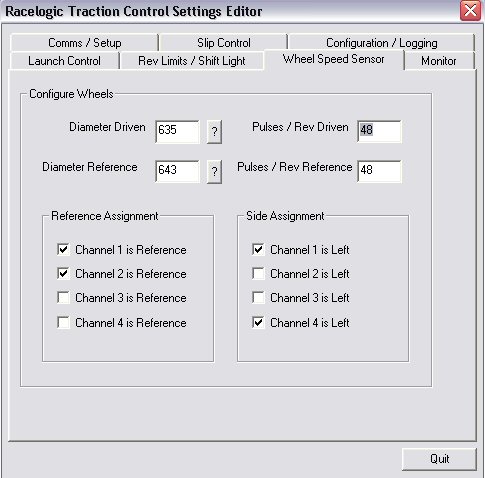
I too have had problems with RLTC setup but have resolved them all. The manual says the following below (see bottom of reply). After reading it you will realise that a total of 4 ticks are required in the "Wheel Speed Sensor" page. ie reference and left wheels. NOT one for each wheel as is often assumed. The reference wheels need to be ticked ie front right and front left; the lefts need to be ticked ie front left and rear left. This means that the front left has two ticks as it is a reference wheel AND a left wheel while the rear right has no ticks as it is neither reference NOR left. After looking at my setup you can easily deduce the setup allocation. see inserted picture Channel 1 - front left (reference & left) Channel 2 - front right (reference NOT left) Channel 3 - rear right (not reference NOT left) Channel 4 - rear left (not reference & left) In order to work out the correct setup as termy has often stated is to jack up the car, spin each wheel noting its channel allocation on the monitor page and then fill in the ticks correctly. You will have to spin the wheels faster than the min speed or change it to a lower level. I didn't - I just spun them as hard as I could and they registered just fine. I have tried to make this explanation clear but if it is not then please speak up - it may be as clear as mud! ATB rltc manual **************************************************** Reference / Driven The system is fully configurable to allow any wheel speed to represent any wheel. This makes life easier when wiring up the system. The box must be informed of which traction control wheel speed channel is connected to which wheel. On a rear wheel drive car, set front channels to ‘Reference’ and rear channels to ‘Driven’. On a front wheel drive car, set the front channels to ‘Driven’ and the rear channels to 'Reference'. Wheel Assignment (FL ,FR ,RL ,RR ) In a similar way to reference/driven wheel assignment the left and the right wheels must be setup. Note : The channels corresponding to front and rear, can be assessed by using the ‘Real time’ function, and spinning each separate wheel in turn. ****************************************************
-
Thanks. I assumed you would need another ECU/AIC of some sort to drive them but never seen anybody talk about this type of mod before. Maybe useful to someone though... ATB
-
Found this on ebay.. http://cgi.ebay.com/ebaymotors/ws/eBayISAPI.dll?ViewItem&category=33554&item=2410665287 Dunno how you would use it. Anybody seen this before? ATB
-
I thought it was a very dubious mod..... Just happened to find this site while surfin around the other day. ATB
-
anybody know what this module does? Checnk out.. http://www.tsunamiracing.co.uk/engine/venom/venom.php Looks dubious.. ATB
-
thanks for the info. think ill bin it as its snapped off anyway ATB
-
Ta
-
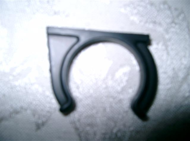
Found this in the passenger footwell today. Anyone know where's it from? I have had the carpet up recently. It's black plastic and looks a bit like a hose clip. ATB
-
I did try the suction cups to the windscreen for a week or so and it worked OK after a fashion. 1. After a while it became a bit of a pain as it is a little difficult to read especially in sunlight. 2. Wires hanging all over the dash. The GPS reciever wire is very long (5metres) and ends up being coiled up everywhere. 3. If you use the cigarette loghter socket for power that too is meesy and in the way. 4. The radar detector itself can be mounted in the windscreen but with the display and the detector it becomes unsightly. Basically the display unit's is very difficult to read when mounted on the screen plus it can come unstuck if your "making progress"! By all means try it for yourself. I initially though the screen mounting was the best option but now it is much much better. All told it took me about 2 hrs to fit. ATB
-
I'd like to see how others have "done it". The trouble with the display unit is it is too thick. if it were about half as thick then it would be much easier to mount it elsewhere. originally I wanted to mount it on the RHS of the dash and I tried a mount that used a stick pad to attatch it to the facia. trouble was under hard cornering/braking and bumps on B roads it soon came loose and wobbled all the time. the mount I used is really solid as it is attatched to a clip on the underside of the dash. ATB
-
the full monty!
.jpg.f4531da80140a6d1efb2ebcb5ed3febd.jpg)
-
metal mounting bracket+plastic mount for display unit. Was tempted to get my Dremmel out and cut off the corners off the metal mount but in the end left it.
.jpg.b06a04e7e2ae9665936c88c0b18225be.jpg)
.jpg.de6a9017f587704571e78831687d0fad.jpg)
.jpg.40bad7b824c0c7655b1947261e02b7ff.jpg)
.jpg.39f91bca0f7322b4f2dfe46484925a88.jpg)


.jpg.f4531da80140a6d1efb2ebcb5ed3febd.jpg)
.jpg.b06a04e7e2ae9665936c88c0b18225be.jpg)